What is pump cavitation? Causes, warning signs and how to prevent it
The noise is usually the first thing you notice: a constant crackling, as if the pump were moving gravel rather than liquid. Then come the vibration and a fluctuating discharge pressure and, weeks or months later, an impeller with a pitted surface and a mechanical seal that no longer seals. Behind that sequence there is almost always the same phenomenon: pump cavitation, one of the most common — and most avoidable — failure modes of centrifugal pumps.
Cavitation is not a manufacturing defect. It is a problem of the relationship between the pump and its installation: it occurs when the pressure at the impeller inlet drops below the vapour pressure of the liquid. That is why it is solved with data — temperature, tank level, friction losses, NPSH — rather than by blindly replacing the pump.
In this guide we explain what physically happens inside the pump, what cavitation damage to expect, how to tell cavitation apart from the problems it is confused with, how to calculate the NPSH margin and which measures eliminate it, both in existing installations and in new projects. We focus on a particularly demanding case: pumping acids, alkalis and other corrosive fluids with thermoplastic pumps, which is the field in which Tecnium Pumps works.
What pump cavitation is and why it is so destructive
The physics: vapour pressure, bubbles and implosion
Every liquid has a vapour pressure: the pressure below which it starts to boil at a given temperature. Water at 20 °C boils if the absolute pressure drops to around 2.3 kPa; at 80 °C it only needs to drop to around 47 kPa. In other words, the hotter the liquid, the more easily it boils without any heat being added.
In a centrifugal pump, the lowest-pressure point in the whole system is not in the pipework but in the eye of the impeller, right at the leading edge of the vanes. There the liquid accelerates and its static pressure falls. If the local pressure at that point drops below the vapour pressure, the liquid vaporises and small vapour cavities form — hence the name of the phenomenon.
The problem is not how the bubble is born but how it dies. The flow carries the bubbles into areas of the impeller passage where the pressure rises again; there the vapour condenses abruptly and the bubble collapses in microseconds. Each implosion produces a micro-jet of liquid and a pressure wave that strikes the vane surface. Millions of impacts, always concentrated in the same area, are enough to tear material away from any substrate: cast iron, stainless steel or thermoplastic.
It is worth distinguishing true cavitation — vaporisation caused by a lack of pressure — from two phenomena that mimic it: suction recirculation, which appears when the pump runs at flow rates well below its design point, and air or gas entrainment in the suction line. All three damage the pump and make noise, but each is corrected differently, so the diagnosis matters.
Cavitation damage: impeller, mechanical seal and bearings
Cavitation damage is usually visible to the naked eye as soon as the pump is opened. These are the components that suffer most:
Cavitation rarely destroys a pump overnight: it wears it down progressively. That is why it is detected late, when the bill already includes the impeller, the seal, the bearings and hours of lost production.
Why cavitation is worse with corrosive fluids
In a cold-water pump, cavitation is mainly a problem of noise, erosion and efficiency. When chemicals are being pumped, three aggravating factors come into play:
This is why, when pumping aggressive fluids in the chemical industry or in steel and surface treatment, cavitation is not just a hydraulic problem: it is a reliability and safety problem, because it usually ends in a seal failure and a product leak.
Causes and symptoms of cavitation in centrifugal pumps
Insufficient suction pressure: the usual causes in the installation
Almost every cause of cavitation comes down to one thing: the suction pressure reaching the impeller eye is lower than the pump needs. That shortfall can originate in the installation, in the fluid itself or in the way the pump is operated:
| Cause | What happens | Typical example |
|---|---|---|
| Excessive suction lift | The pump sits above the liquid level and uses up pressure lifting it | A surface-mounted pump emptying a pit or a buried tank |
| Friction losses in the suction line | Long or narrow pipework, bends, dirty strainers or partly closed valves reduce pressure before the flange | A blocked Y-strainer or a bend right at the suction flange |
| Liquid temperature | Vapour pressure rises and the liquid boils sooner | Recirculation of hot surface-treatment baths |
| Low tank level | The liquid column shrinks and a vortex can form | The final stage of emptying a storage tank |
| Closed or vacuum tank | The pressure on the liquid surface is below atmospheric | Suction from an evaporator or a tank with a blocked vent |
| Site altitude | Less atmospheric pressure is available | At 1,000 m above sea level, around 1.2 m less is available than at sea level |
| Flow above the design point | The NPSH required by the pump rises with flow | A pump running with no back-pressure and an empty discharge line |
| Very low flow | Suction recirculation and heating of the liquid | A pump running against an almost closed discharge valve |
A very common mistake on site is controlling the flow by throttling the suction valve. The suction valve must always be fully open: flow should be controlled on the discharge side or, better still, with a variable speed drive (VSD).
How to recognise a cavitating pump: noise, vibration and loss of head
The symptoms of cavitation are characteristic but not exclusive. This table helps to separate classic cavitation from the two problems it is most often confused with:
| Symptom | Cavitation from insufficient NPSH | Low-flow recirculation | Air or gas entrainment |
|---|---|---|---|
| Noise | Crackling, like gravel; increases with flow | Irregular knocking at low flow | Variable, with gurgling |
| Discharge pressure | Drops and fluctuates | Fluctuates | Fluctuates; the pump may lose its prime |
| Damaged area of the impeller | Low-pressure side of the vane, near the leading edge | Pressure side of the vane, near the eye | No typical pitting |
| When the discharge is throttled slightly | Noise decreases | Noise increases | Little change |
| Correction | Increase NPSHa or reduce NPSHr | Bring the flow closer to the design point | Eliminate air ingress and ensure submergence |
The definitive check is to measure. A compound gauge on the suction flange allows you to calculate the real NPSH available with the pump running: convert the reading to absolute pressure and metres of liquid column, add the velocity head at the flange and subtract the vapour pressure at the operating temperature. If the result approaches the NPSH required shown on the pump curve for that flow, the diagnosis is clear.
Vibration also provides clues: cavitation produces broadband vibration with no clear dominant frequency, unlike imbalance or misalignment, which show up at specific frequencies linked to the running speed.
NPSH margin: the calculation that separates a healthy pump from a cavitating one
NPSH (Net Positive Suction Head) is the tool for comparing what the installation offers with what the pump needs:
NPSH available is calculated as follows, with all terms in metres of column of the pumped liquid:
NPSHa = (Pa − Pv) / (ρ · g) ± Hz − Hf
Where Pa is the absolute pressure on the liquid surface, Pv the vapour pressure at the operating temperature, ρ the density, Hz the height difference between the liquid surface and the pump centreline (positive with flooded suction, negative with suction lift) and Hf the friction losses in the suction line.
The most underestimated term is vapour pressure, because it rises very quickly with temperature:
| Water temperature | Vapour pressure (kPa abs.) | Equivalent in metres of column |
|---|---|---|
| 20 °C | 2.3 | 0.24 m |
| 40 °C | 7.4 | 0.76 m |
| 60 °C | 19.9 | 2.07 m |
| 80 °C | 47.4 | 4.97 m |
| 90 °C | 70.2 | 7.41 m |
These values are for water; dilute aqueous solutions behave similarly, but with concentrated acids, solvents or mixtures you must use the vapour pressure of the actual product, which can be very different.
Let us look at an example with an open tank at sea level, a pump located 3 m above the minimum liquid level, 1 m of suction losses and a pump with an NPSHr of 3 m at the duty point:
| Scenario | NPSHa | Margin | Result |
|---|---|---|---|
| 20 °C, pump 3 m above the liquid level | 6.1 m | +3.1 m | Correct operation |
| 60 °C, same installation | 4.4 m | +1.4 m | Acceptable, with little margin if the level drops |
| 80 °C, same installation | 1.7 m | −1.3 m | Cavitation certain |
| 80 °C, pump 2 m below the liquid level (flooded suction) | 6.7 m | +3.7 m | Correct operation |
The same pump, in the same installation, goes from running correctly to cavitating simply because the temperature has changed. And lowering the pump by two metres solves the problem without touching the equipment.
How much margin should you allow? As a practical guide, many projects work with an NPSHa that exceeds NPSHr by at least 0.5–1 m and, in relative terms, by 10–30 % or more. The Hydraulic Institute’s ANSI/HI 9.6.1 guideline recommends margins by type of application, which are stricter for critical duties, hot fluids and pumps with high suction energy. With corrosive fluids, where a seal failure means a leak of aggressive product, it pays to stay at the upper end of those margins.
How to prevent pump cavitation: installation fixes and pump selection
Corrective measures and selection criteria to eliminate cavitation
There are only two ways to gain margin: increase the NPSH available or reduce the NPSH required. This table ranks the most effective measures from least to most effort:
| Measure | Acts on | Effort |
|---|---|---|
| Open suction valves fully and clean strainers | NPSHa (lower losses) | Low |
| Bring the pump back to a flow close to its best efficiency point (BEP) | NPSHr | Low |
| Raise the minimum tank level and adjust the level alarms | NPSHa | Low |
| Increase the suction pipe diameter, remove bends and fit the eccentric reducer flat side up | NPSHa | Medium |
| Reduce the running speed with a variable speed drive | NPSHr | Medium |
| Cool the liquid or place the pump upstream of the heat exchanger | NPSHa (lower vapour pressure) | Medium |
| Install the pump with flooded suction, below the tank level | NPSHa | Medium-high |
| Switch to a vertical pump with a submerged casing or to a model with lower NPSHr | Both | High (project) |
When designing the suction pipework, three rules prevent most problems: low velocities (as a guide, below 1.5–2 m/s), a straight run of several pipe diameters before the flange, with no bends or valves right next to the pump, and no high points where pockets of air or gas can collect. Reducing the running speed is also very effective: the NPSH required falls roughly with the square of the speed.
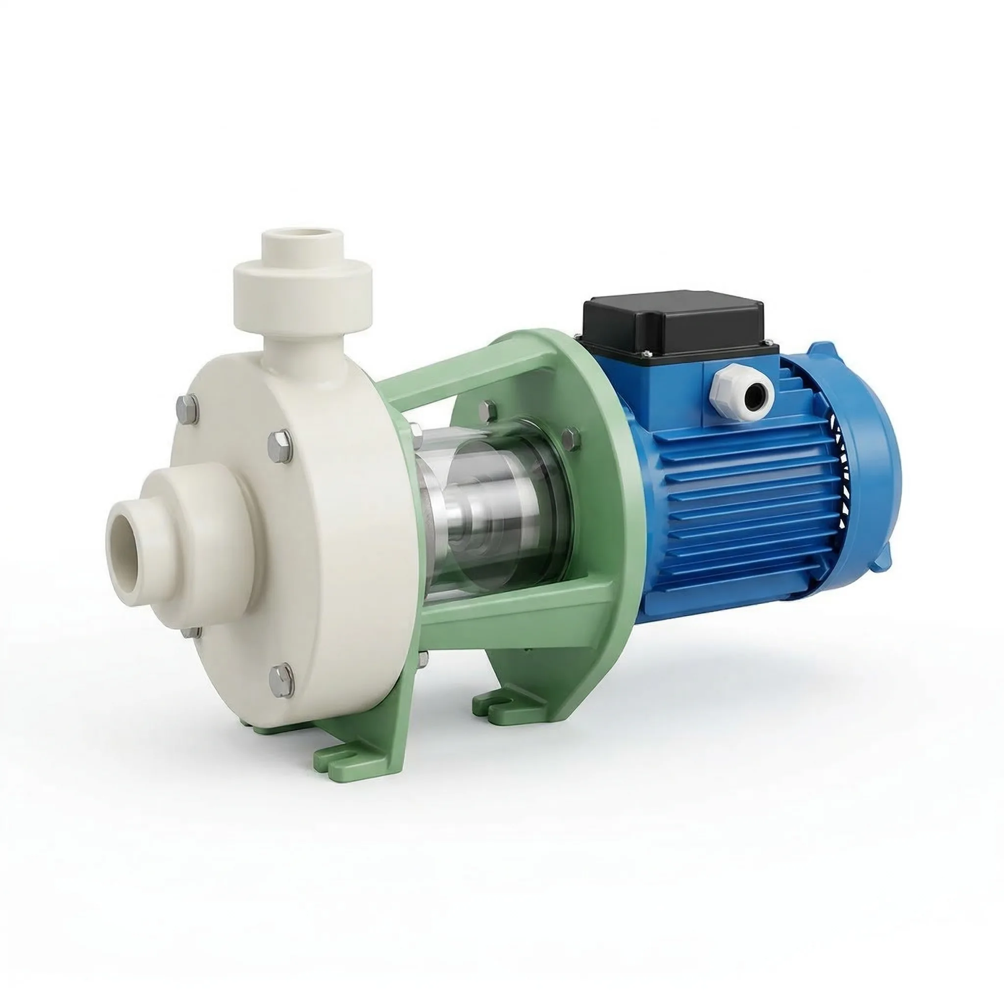
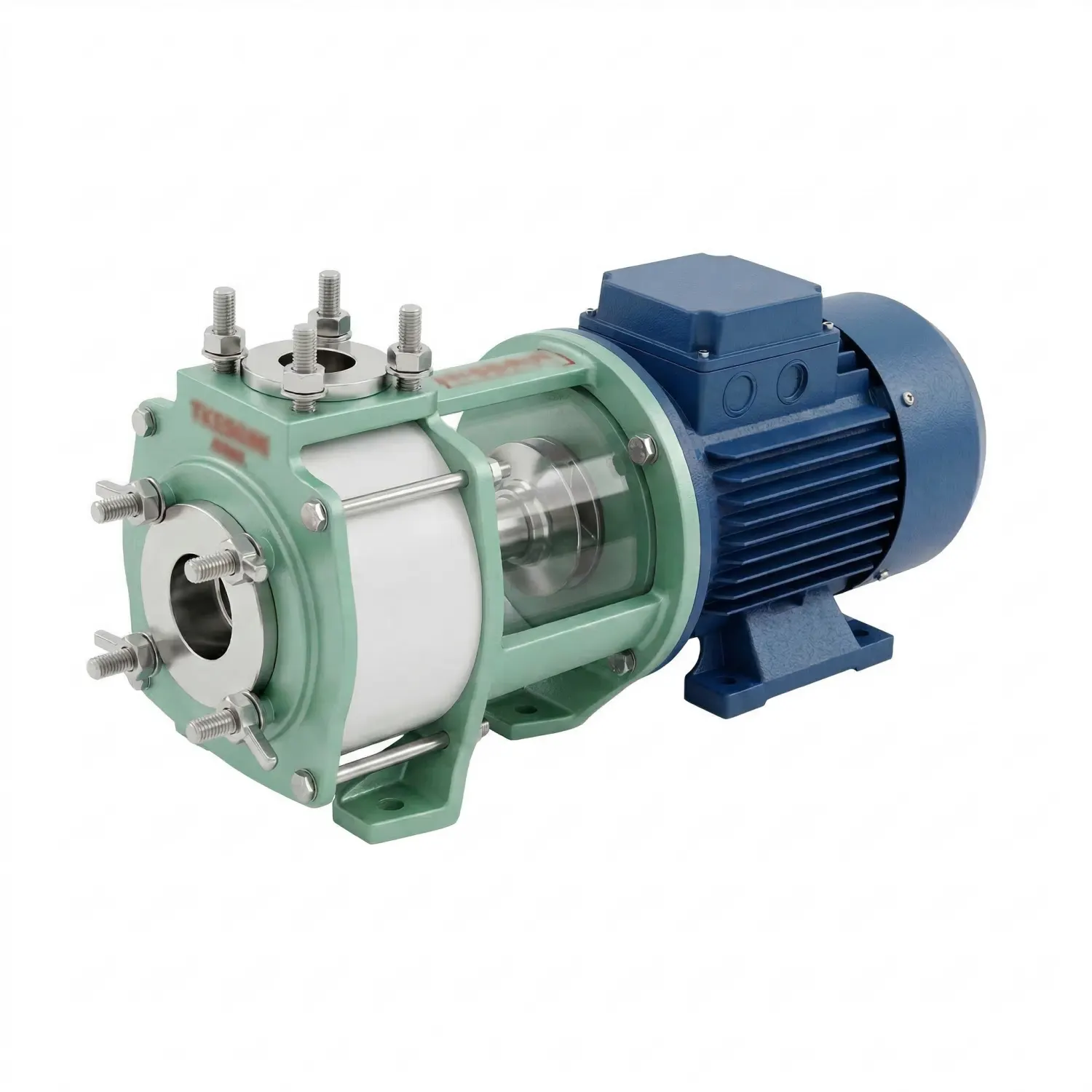
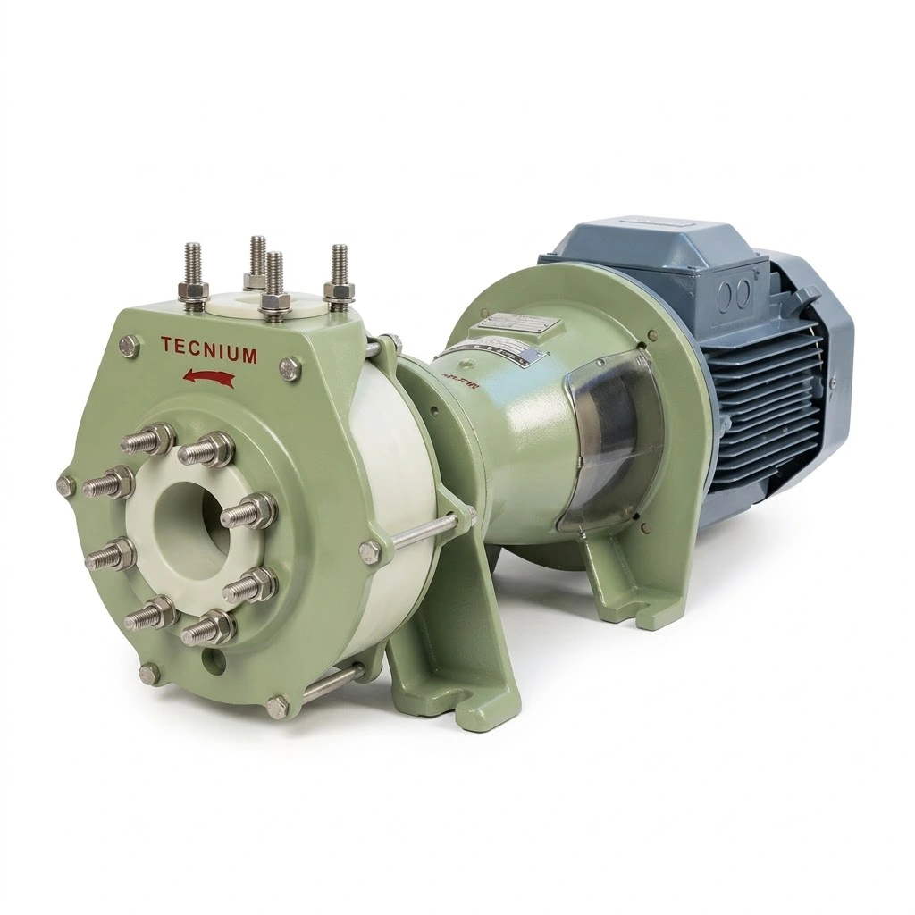
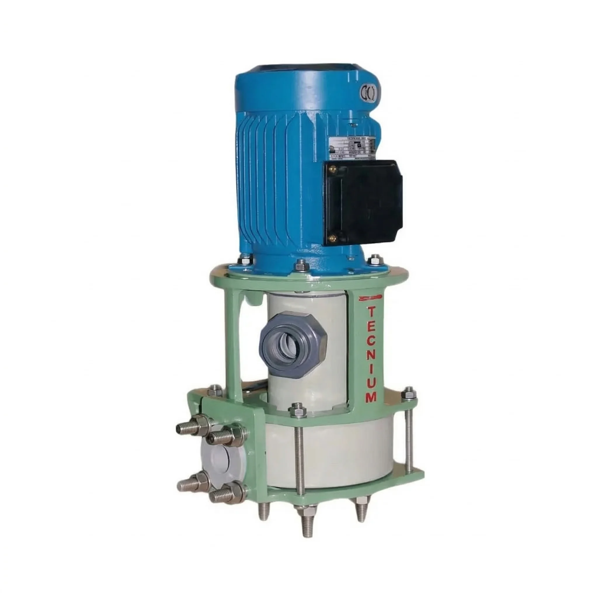
In new projects, the most reliable way to prevent cavitation is to choose a pump configuration that does not depend on suction. The Tecnium Pumps range of plastic pumps offers several answers depending on the installation:
The material also matters, because it determines the operating temperature and therefore the vapour pressure. According to Tecnium’s technical data, PP retains its mechanical stability up to 90 °C, PE up to 80 °C, PVDF up to 120 °C and E-CTFE up to 150 °C in continuous service. The closer you operate to those limits, the more important it is to verify the NPSH margin.
Pump cavitation: frequently asked questions
Do you suspect one of your pumps is cavitating, or are you specifying a new installation? Send our technical team the fluid and its concentration, the maximum temperature, the required flow and head, the minimum liquid level relative to the pump and a sketch of the suction line. With that information we will check the NPSH margin and propose the right configuration. Request your free quote.
continue reading